Product Description
Low Backlash Worm Gearbox Efficiency Servo Gear Boxes reducer zero electric transmission motor China Manufacturers for Energy Aerospace Industrial Gearboxes
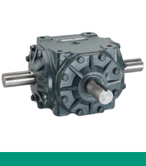
The low backlash drive units HPCNHS type are available in 4 sizes. Each size includes 2 ratios which are 30:1 and 60:1.
The drive units HPCNHS are built with a minimum backlash which can be adjusted due to the duplex toothing of the gears.
The low backlash drive units are built for medium power transmission.
Worm Gear Units:
The NHS-Range gearboxes is available in 4 model sizes and 2 standard ratios.The gearbox size is identical to the centreline distance.
Low backlash Features :
— Worm gear gyration backlash can be adjusted to less than 1 arc.
— Reducer can be re-adjusted the gap after using .
— Input with coupling : reliable without backlash .
— Output using conical clamping ring couplings : reliable without backlash.
| Application: | Motor, Electric Cars, Motorcycle, Machinery, Marine, Agricultural Machinery, Car |
|---|---|
| Function: | Distribution Power, Clutch, Change Drive Torque, Change Drive Direction, Speed Changing, Speed Reduction, Speed Increase |
| Layout: | Coaxial |
| Hardness: | Hardened Tooth Surface |
| Installation: | Horizontal Type |
| Step: | Three-Step |
| Samples: |
US$ 9999/Piece
1 Piece(Min.Order) | |
|---|
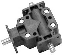
Common Industries and Applications of Miter Gearboxes
Miter gearboxes are widely used across various industries due to their unique capabilities in transmitting motion at a 90-degree angle. Some common industries and applications include: Automotive (steering systems, robotics, machinery, aerospace, construction equipment, marine, medical equipment). The versatility of miter gearboxes to efficiently change the direction of motion and transmit power at right angles makes them valuable components in various industries where precise motion control and compact design are essential.
Proper Installation and Alignment of Miter Gearboxes:
Installing and aligning a miter gearbox correctly is crucial to ensure optimal performance and longevity. Here’s a step-by-step guide on how to do it:
- Preparation: Gather all the necessary tools and equipment for the installation, including mounting hardware, shims, and measuring instruments.
- Positioning: Place the miter gearbox in the desired location, ensuring that it is level and securely supported. Use appropriate mounting brackets or plates to secure the gearbox to the mounting surface.
- Shaft Alignment: Align the input and output shafts of the miter gearbox with the shafts of the connected equipment. Check that the shafts are parallel and collinear for proper alignment.
- Check Tolerance: Measure the axial and radial alignment tolerances between the gearbox and connected equipment. Use precision measuring tools such as dial indicators or laser alignment systems to ensure accurate measurements.
- Adjustment: If alignment tolerances are not within the specified range, make necessary adjustments using shims or other alignment techniques. Gradually add or remove shims as needed to achieve proper alignment.
- Bolt Tightening: Once the miter gearbox is properly aligned, gradually tighten the mounting bolts or fasteners in a crisscross pattern to evenly distribute the load. Use the recommended torque specifications provided by the gearbox manufacturer.
- Lubrication: Apply the recommended lubricant to the gearbox according to the manufacturer’s guidelines. Proper lubrication is essential for minimizing friction and ensuring smooth operation.
- Testing: Before fully operating the system, perform a test run of the miter gearbox to ensure that it operates smoothly and without any abnormal vibrations or noise.
- Final Checks: Double-check the alignment, bolt tightness, and lubrication after the test run. Make any necessary adjustments before putting the system into full operation.
Proper installation and alignment are critical for maximizing the efficiency, reliability, and lifespan of miter gearboxes. Following these steps and consulting the manufacturer’s guidelines will help ensure optimal performance of the gearbox and the entire mechanical system.
Types of Miter Gearboxes and Their Differences
There are two main types of miter gearboxes: straight miter gearboxes and spiral miter gearboxes.
Straight Miter Gearboxes: In straight miter gearboxes, the bevel gears have teeth that are cut straight across the gear’s face. This design allows for efficient power transmission and is suitable for applications where precise motion redirection is required. However, straight miter gearboxes may produce more noise and vibration due to the nature of the gear tooth engagement.
Spiral Miter Gearboxes: Spiral miter gearboxes use bevel gears with spiral-cut teeth. The spiral angle of the teeth helps to reduce noise and vibration by providing smoother tooth engagement and gradual contact between the gear teeth. This design is especially beneficial for applications where quieter operation and improved durability are desired.
The choice between straight and spiral miter gearboxes depends on the specific requirements of the application, including the desired level of noise, vibration, and efficiency. Both types of miter gearboxes offer the same fundamental motion transmission principle, but the design differences impact their performance characteristics.


editor by CX 2023-10-12